

Magnetic Field Of A Capacitor
Nosotros wish to find the magnetic field in the plane we've shown in the representations. Nosotros know from the notes that a changing electric field should create a curly magnetic field. Since the capacitor plates are charging, the electric field betwixt the ii plates will be increasing and thus create a curly magnetic field. Nosotros will retrieve well-nigh ii cases: one that looks at the magnetic field inside the capacitor and one that looks at the magnetic field outside the capacitor.
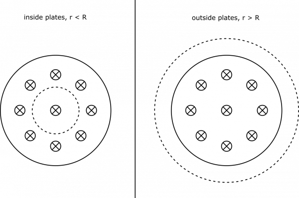
Due to the round symmetry of the problem, we choose a circular loop in which to situate our integral $\int \vec{B}\bullet\text{d}\vec{l}$. Nosotros besides choose for the loop to be the perimeter of a apartment surface, so that the unabridged affair lies in the airplane of involvement, and there is no enclosed current (so $I_{enc} = 0$ - there is only the irresolute electric field). We show the drawn loop below, split into two cases on the radius of the loop.
![]()
Circular Loops
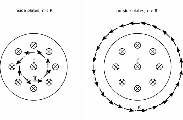
Below, nosotros also depict the direction of the magnetic field forth the loops. We know the magnetic field is directed along our round loop (since the changing electric flux creates a curly magnetic field) – if it pointed in or out a fiddling flake, we may exist able to excogitate of the closed surface with magnetic flux through it, which would imply the being of a magnetic monopole. This cannot be the instance! We also know that the field is directed counterclockwise, due to the increasing electric field into the page. (This comes from an extension of Lenz's Law, but will non needed for this course).
![]()
Circular Loops, with B-field shown
We are pretty well prepare to simplify our calculation of the integral in the representations, since the B-field is parallel to the loop'south perimeter. Below, we show the integral calculation, where the magnetic field at a radius $r$ is displayed equally $B(r)$.
$$\int \vec{B} \bullet \text{d}\vec{l} = \int B(r) \text{d}l = B(r) \int \text{d}l = ii\pi r B(r)$$
Adjacent, we need to observe the changing electric flux in our loop. Since our loop was described with a flat surface, and the electrical field is directed parallel to the area-vector of the loop, we can write electrical flux as $\Phi_E = \vec{E} \bullet \vec{A} = EA$. This formula will need to be split up for parts of the surface inside the plates versus outside, since the electric field is dissimilar.
$$\Phi_\text{Due east, in} = EA = \frac{Q/A_{\text{plate}}}{\epsilon_0}A_{\text{loop}} = \frac{Q}{\epsilon_0\pi R^2}\pi r^2 = \frac{Qr^2}{\epsilon_0 R^2}$$ $$\Phi_\text{E, out} = EA = E_\text{in}A_\text{in} + E_\text{out}A_\text{out} = \frac{Q/A_{\text{plate}}}{\epsilon_0}A_{\text{plate}} + 0 = \frac{Q}{\epsilon_0\pi R^2}\pi R^2 = \frac{Q}{\epsilon_0}$$
Now, if we wish the observe the change in flux, nosotros will have a time derivative. Notice that all the terms in the flux expressions above are constant, except for $Q$, which is changing with time as dictated by $I$.
$$\frac{\text{d}\Phi_E}{\text{d}t} = \frac{\frac{\text{d}Q}{\text{d}t}r^2}{\epsilon_0 R^2} = \frac{Ir^2}{\epsilon_0 R^2} \text{, inside, } r<R$$ $$\frac{\text{d}\Phi_E}{\text{d}t} = \frac{\frac{\text{d}Q}{\text{d}t}}{\epsilon_0} = \frac{I}{\epsilon_0} \text{, exterior, } r>R$$
Nosotros tin can now connect the pieces together (think, $I_{enc}=0$, so nosotros omit information technology below). We can write:
$$2\pi r B(r) = \int \vec{B}\bullet \text{d}\vec{l} = \mu_0\epsilon_0\frac{\text{d}\Phi_E}{\text{d}t} = \mu_0 \frac{Ir^2}{R^2} \text{, inside, } r<R$$ $$2\pi r B(r) = \int \vec{B}\bullet \text{d}\vec{l} = \mu_0\epsilon_0\frac{\text{d}\Phi_E}{\text{d}t} = \mu_0 I \text{, outside, } r>R$$
We are gear up to write out the magnetic field.
\[ B(r) = \begin{cases} \frac{\mu_0 I r}{2\pi R^2} &&& r<R \\ \frac{\mu_0 I}{2\pi r} &&& r>R \end{cases} \]
Notice, the distance betwixt the plates has no effect on the magnetic field adding. Also, the amount of the charge on the plates at a given time does not matter – nosotros only care near how fast the charge is irresolute (the current!). Also, it is interesting that exterior the plates, the magnetic field is the aforementioned as it would be for a long wire. This would be just as if the capacitor were non there, and the wire were connected. Below, we show a graph of the magnetic field strength as a function of the distance from the eye of the capacitor.

![]()
B-Field Strength, Graphed
We accept enough information to find the maximum B-field, which is at the edge of the plates: $$B_{\text{max}} = \frac{\mu_0 I}{2\pi R} = \frac{4\pi \cdot 10^{-7} \text{Tm/A} \cdot three\text{ A}}{2\pi \cdot 10 \text{ m}} = 60 \text{ nT}$$

Magnetic Field Of A Capacitor,
Source: http://msuperl.org/wikis/pcubed/doku.php?id=184_notes%3Aexamples%3Aweek14_b_field_capacitor
Posted by: brittainverea1994.blogspot.com
0 Response to "Magnetic Field Of A Capacitor"
Post a Comment